Graphics-Ch7. Viewing
Graphics-Ch7. Viewing
Intro
- 3D to 2D mapping을 통해 object를 3d location과 2D view 사이에서 이동시키는 것을 “viewing Transformation“이라고 함
- object-order rendering에서 중요함
- ch4(Ray-Tracing)단원에서 orthographic(paralled) view와 perspective view에서 vieweing ray가 어떻게 생성되는지에 대해 간단하게 다루었음
- ray-tracer는 ray와 만나는 가장 가까운 교차점에 대한 surface를 찾는 것이고, object-order renderer는 solid-looking object에서 어떤 표면이 screen space(pixcel space)의 어떤 점들에 매칭되어 그려지는지에 대해 다루는 것
1. Viewing Transformations
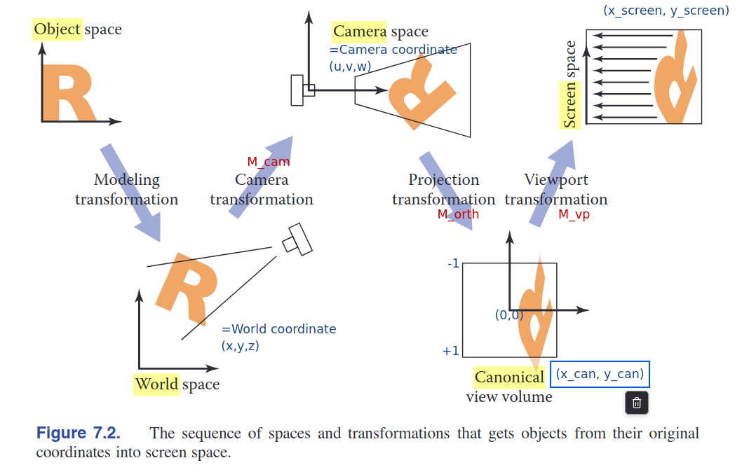
- Viewing Transformation을 통해 Canonical Coordinate System에서의 $(x, y, z)$로 표기되는 3D location을 이미지 픽셀 단위의 screen space 매핑하는 것이 필요함
- 고려되어야 할 것 : projection의 종류, FOV(Field of View, 시야각), 이미지 해상도 등
- 아래 세 가지의 transformation 과정으로 World Space에 있는 물체가 Screen Space로 View Transformed된다.
- Camera Transformation (Eye Transformation) :
- camera의 pose(position, oriendtation)에만 의존
- World Coordinate -> Camera Coordinate
- Projection Tranformation :
- projection 종류에 의해서만 의존
- Camera space -> Canonical View Volume
- -1에서 +1 범위의 points
- Viewpoint Transformation (Windowing Transformation) :
- output 이미지의 size와 position에 의존
- Canonical view volume -> Screen space
- Camera Transformation (Eye Transformation) :
1.1. The Viewport Transformation
- canonical view volume에 있는 view를 가정해아 함, input처럼 생각
$(x, y, z) \in [-1, +1]^3$
\[\begin{bmatrix} x_{\text{screen}} \\ y_{\text{screen}} \\ 1 \end{bmatrix} = \begin{bmatrix} \frac{n_x}{2} & 0 & \frac{n_x - 1}{2} \\ 0 & \frac{n_y}{2} & \frac{n_y - 1}{2} \\ 0 & 0 & 1 \end{bmatrix} \begin{bmatrix} x_{\text{canonical}} \\ y_{\text{canonical}} \\ 1 \end{bmatrix} .\]
- Viewport Transformation Matrix :
- 앞선 식의 변환행렬에다가 $z$ coordinate의 행과 열에 $ [0 \quad 0 \quad 0 \quad 1]$ 를 추가시킴
1.2. Orthographic Projection Transformation
- canonical view volume 좌표계로 옮기는 변환 과정
- input : camera coordinate (orthographic view)
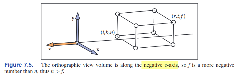
- orthographic view volume을 아래의 3D space로 정의할 수 있음
= $[l,r]$ x $[b,t]$ x $[f,n]$- 좌우, 상하, 앞뒤 절단면을 정의하는 클리핑 파라미터
- 아래 그림처럼 orthorgraphic view volume에서 $-z$방향으로 바라보고 있다고 가정하기 때문에(상황마다 다르게 설정가능하긴 하다) $f$(far)가 $n$(near)보다 작은 값임
camera space(orthographic view volume) => screen space(image pixel)로의 최종 변환 수식은 아래와 같음:
\[\begin{align} \begin{bmatrix} x_{\text{pixel}} \\ y_{\text{pixel}} \\ z_{\text{canonical}} \\ 1 \end{bmatrix} = (M_{\text{vp}}M_{\text{orth}}) \begin{bmatrix}x \\ y \\ z \\ 1\end{bmatrix}.\end{align}\]
1.3. The Camera Transformation
- World(object) space 에서 Camera Space($uvw$-space)로의 변환 과정
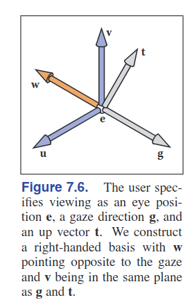 | 새롭게 정의되는 변수 3가지 = {eye position $e$, gaze direction $g$, view-up vector $t$} + 기저 벡터 ${uvw}$ 이 정보들로 왼쪽처럼 coordinate system 세팅하는데 충분한 정보를 제공함 |
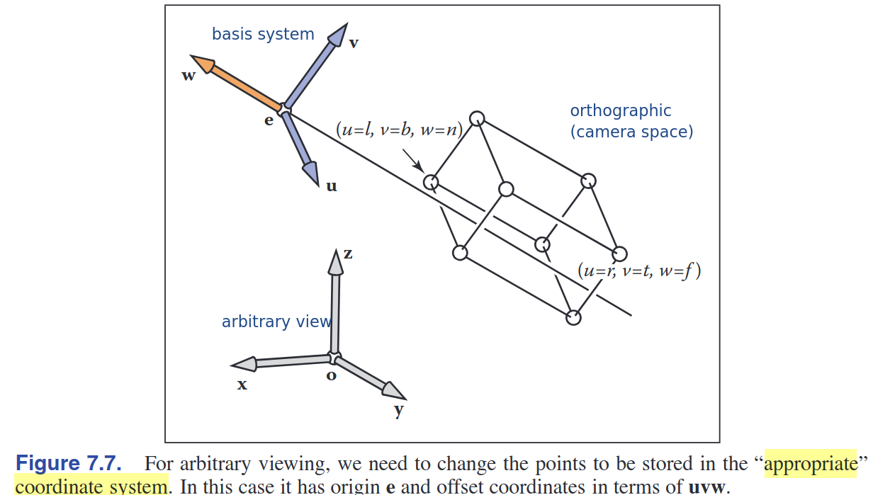
- arbitrary view(world space coordinate $xyz$)으로부터 origin $e$와 기저벡터 $u,v,w$로 표현된 카메라 좌표 시스템으로 저장하는 것이 목표
- origin $e$로의 translation & u,v,z로의 scaling matrix 처럼 생각하면 됨 (왼에서 오로 곱해지는 그거)
아래의 변환 수식을 통해 수행됨:
\[\begin{align} M_{\text{cam}} = \begin{bmatrix} \mathbf{u} & \mathbf{v} & \mathbf{w} & \mathbf{e} \\ 0 & 0 & 0 & 1 \end{bmatrix}^{-1} = \begin{bmatrix} x_u & y_u & z_u & 0 \\ x_v & y_v & z_v & 0 \\ x_w & y_w & z_w & 0 \\ 0 & 0 & 0 & 1 \end{bmatrix} \begin{bmatrix} 1 & 0 & 0 & -x_e \\ 0 & 1 & 0 & -y_e \\ 0 & 0 & 1 & -z_e \\ 0 & 0 & 0 & 1 \end{bmatrix}. \end{align}\]- 최종적인 Viewing Transformation 알고리즘 :
| Matrix Name | Description |
|---|---|
| M_vp | Viewport Matrix |
| M_orth | Orthographic Matrix |
| M_cam | Camera Matrix |
| M | $( M = M_{\text{vp}} M_{\text{orth}} M_{\text{cam}} )$ |
Algorithm
- Construct ( $M_{\text{vp}}$ )
- Construct ( $M_{\text{orth}}$ )
- Construct ( $M_{\text{cam}}$ )
- Compute ( $M = M_{\text{vp}} M_{\text{orth}} M_{\text{cam}}$ )
- For each line segment ( (a_i, b_i) ):
- Compute ( $p = M_{a_i}$ )
- Compute ( $q = M_{b_i}$ )
- Draw line from ( $(x_p, y_p)$ ) to ( $(x_q, y_q)$ )
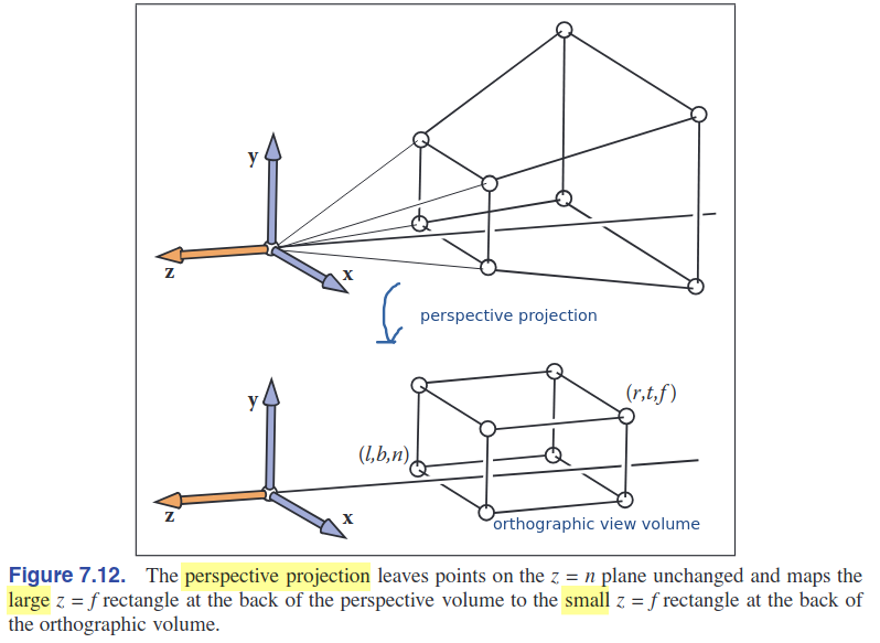
2. Projective Transformations
- 앞선 1.2.단계의 orthographic veiw volume(camera space)에서 canonical view volume으로 변환 하는 단계에서 사용하는 transformation 종류들에 대해서 알아보자.
- 주요 특성(key property) :
- screen에 보이는 object의 size는 $-z$축 방향으로 보여지는 camera space와의 거리(depth) $z$의 역수에 비례함
Affine Transformation(어파인 변환)으로는 분모로 z(input vector의 한 요소)를 나누는 이러한 연산은 구현할 수가 없다
- Homogeneous Coordinate 메커니즘을 활용함
- 마지막 원소를 1로 두고 차원을 하나 확장시키는 좌표계 $(x,y,z) -> (x,y,z,1)$
- 여기서 1을 $(x,y,z)$좌표의 분포로 생각할 수 있다.
- Affine 변환을 통해 변환된 point $x’ = ax + by + cz +d$
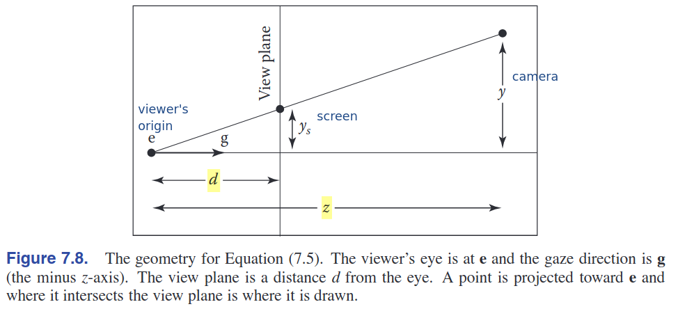
3. Perspective Projection
matrix transformation : \(\begin{bmatrix} y_s \\ 1 \end{bmatrix} \sim \begin{bmatrix} d & 0 & 0 \\ 0 & 1 & 0 \end{bmatrix} \begin{bmatrix} y \\ z \\ 1 \end{bmatrix}.\)
Perspective Matrix $P$ :
\(\begin{align} \mathbf{P} = \begin{bmatrix} n & 0 & 0 & 0 \\ 0 & n & 0 & 0 \\ 0 & 0 & n + f & -f n \\ 0 & 0 & 1 & 0 \end{bmatrix}.\end{align}\)
- perspective matrix를 orthograpic 시스템에 병합하기 위해서, $M_{per} = M_{orth} P.$를 이용하여 아래와 같은 transforamtion matrix 로 분해할 수 있다:
- \[\begin{align} M = M_{vp} (M_{orth} P) M_{cam} \end{align}\]
- \[\begin{align} M_{\text{per}} = M_{orth} P = \begin{bmatrix} \frac{2n}{r - l} & 0 & \frac{l + r}{l - r} & 0 \\ 0 & \frac{2n}{t - b} & \frac{b + t}{b - t} & 0 \\ 0 & 0 & \frac{f + n}{n - f} & \frac{2fn}{f - n} \\ 0 & 0 & 1 & 0 \end{bmatrix}. \end{align}\]
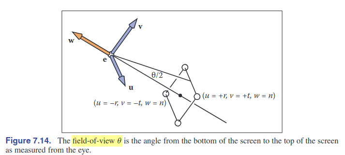
5. Field-of-View(FOV)
- 한국말로 시야각이라는 의미
- $\theta$로 표현 = the angle from the bottom of the screen to the top of the screen as measured from the eye
This post is licensed under CC BY 4.0 by the author.